We hear about “RF in my shack” or “I’ve got a hot mic” and similarly vague and disturbing images and stories. What is actually happening here?
If you have “RF in your shack” where devices disconnect or start acting weird as soon as you transmit, or if you’ve ever felt your lips tingle (or worse) when they touch a microphone. This is caused by high levels of RF energy in your shack. We don’t want RF in our shack, we want it inside transmission lines, through our antenna, and out into the world for someone else to receive.
What is Common Mode Current?
It’s useful to think of Common Mode current in regards to its opposite: Differential Mode current.
A transmission line is two electrical conductors run next to each other that carry energy from one place to another. For example: the center conductor and shield of a coaxial cable. Or the two wires in your DC power cable. The important part is that there are two conductors, and that they carry current in opposite directions, completing the loop between the power source and the load.
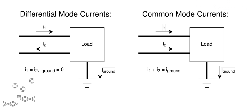
Currents are Differential Mode when they are the exact same amount, in opposite directions. If one conductor has 1A flowing in one direction and the other conductor has 1A flowing in the opposite direction, those currents are said to be Differential: exactly matched or balanced, in opposite directions.
Current is Common Mode when it only flows one direction. For example: the current flowing in one wire of an antenna, or if you look at only half of the transmission line.
You can have both Differential Mode and Common Mode flowing on the same transmission line at the same time. In our earlier example, if we instead had 3A flowing one direction and only 2A flowing the other direction, this would be 2A of Differential Mode current, and 1A of Common Mode current. The matched amount of current are Differential Mode, and whatever is left over is Common Mode.
What’s the difference?
Current flows in a loop. What current goes into a device must come out of it somewhere. We want that “somewhere” to be the transmission line we’re using to send that current. If it’s not, then it’s going somewhere else; sometimes that “somewhere else” is through you, the operator, to ground.
We want all our RF to stay Differential Mode and stay in our transmissions lines.
Where do these currents flow?
Antenna Wires
One place we want Common Mode is on antenna wires. Consider a dipole antenna: each side of the dipole antenna has current only flowing in one direction at a time. The matched balancing current is flowing on the other half of the antenna.
As a whole, the antenna is Differential Mode. But each individual wire only has Common Mode current on it. This becomes important later.
Coaxial Transmission Lines
An interesting characteristics of coaxial cable is:
- Differential Mode currents ALWAYS flow on the inside of the coax. The opposite currents setup EM fields that pull the currents towards each other on the inside.
- Common Mode currents ALWAYS flow on the outside of the shield of the coax. Without a balancing current to pull it inside, skin effect takes over and pushes common mode current to the outside of the shield.
Always means ALWAYS. See below for an interesting thought experiment about this.
Parallel Transmission Lines
The same properties of Differential Mode and Common Mode discussed below apply to both parallel and coaxial transmission lines. The mechanisms are slightly different, but once you get away from the near field of a parallel transmission line, it works just like coax. But, ya know, with less loss.
I find it easier to visualize by talking about coax. But note that all the below applies to twin lead too.
What causes Common Mode currents?
Common Mode current can come from many places, but there are two common sources that we’ll deal with in amateur radio. One is while we’re transmitting, the other is while we are receiving.
Transmitting: Asymmetric Antennas
Consider a conventional transmitter, sending 100W (+50dBm) of RF energy through a transmission line. It’s Differential Mode, therefore it stays on the inside of the coax where we want it. At the far end of the transmission line is an antenna that takes that 100W of RF energy and makes ripples in the electromagnetic field for someone else to detect. If that antenna is perfectly matched and symmetric, then all of that 100W will turn into ripples in the EM field, and we’re in good shape.
There is no such thing as a perfectly matched and symmetric antenna, there will always be SOME amount of mismatch and asymmetry. That mismatch and asymmetry causes some amount of that 100W of Differential Mode current to reflect back down the transmission line to the transmitter.
The Differential Mode parts of the reflected current travel on the inside of the coax and show up as a high SWR. The Common Mode parts of the reflected current travel on the outside of the coax, over the shield of your radio, over the shield of your microphone, over the spark-gap between the microphone and your lips, through your body and shoes to ground. For example.
We don’t like tingling lips, so we want to stop this.
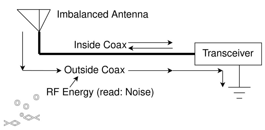
Receiving: Transmission Line as Antenna
Consider an antenna connected to a transmission line, thence to a receiver, listening for weak signals in the range of -100dBm to -120dBm. To minimize transmission line length, we had to run the transmission line straight across our laundry room, next to our washer/dryer, and the LED lighting in our kitchen, before it makes it to the shack.
The inside of our coax is a shielded environment; no noise can get into it (we’ll assume a perfect shield for the purposes of this discussion).
However, the OUTSIDE of our coax is just a long wire antenna connected directly to our receiver. Ideally, it’s connected to the ground of our receiver, with a perfect zero ohm connection to ground, so all the Common Mode current shunts directly to ground with zero voltage generated.
Just like there’s no such thing as a perfectly symmetric antenna, there’s also no such thing as a perfectly zero ohm ground. Every connection from the shield of your transmission line to ground has SOME impedance. And the Common Mode current from the outside of your transmission line, flowing across that impedance to ground, creates a small voltage. Ohm’s Law: V=IR. If you have a current (I) and an impedance (R), they make a voltage (V). And that voltage shows up as noise in your receiver.
Usually, the current is small, and the impedance is small, so the voltage they create is also small. But our receivers are measuring about -120dBm, which is on the order of 1 microvolt. It doesn’t take much current or much impedance to make 1uV in your receiver.
Ok, you’ve convinced me. How do I get rid of Common Mode Current?
I’m going to wave my hands and pull a magic device out of the hat called a Common Mode Current Choke (aka CMCC). This magic device allows Differential Mode currents to pass right through it unimpeded, but blocks Common Mode current. I’ll show you how the magic trick is done in a sec, but for now just accept that this magic device exists.
Transmitting Common Mode
To prevent Transmitting Common Mode currents, we put a CMCC at the feed point of our antenna. This allows our forward power to get to the antenna (as well as the differential reflected current back down to our transmitter, so this won’t help your SWR), but prevents the Common Mode current from flowing back down the outside of our coax. It raises the impedance of the outside of the coax enough that the antenna, even a mismatched asymmetric antenna, is the preferred path for the current to flow.
Receiving Common Mode
To prevent Receiving Common Mode currents, we put a CMCC at the feed point of our radio. This effectively disconnects the shield of our coax from the receiver. It creates a large impedance in series with the small impedance of the ground connection in the radio, which form a voltage divider so the vast majority of the voltage is dropped across the choke, not your receiver.
To prevent Transmitting Common Mode currents, we put a CMCC at the feed point of our antenna. To prevent Receiving Common Mode currents, we put a CMCC at the feed point of our radio.
How does a Common Mode Current Choke work?
Our magical device that passes Differential Mode current, but blocks Common Mode current. How does that work?
Two things are working together here: Inductors, and Magnetic Fields.
When you pass a current through a wire, it creates a magnetic field around that wire. If you coil the wire up, those magnetic fields add together and get stronger. If that current stops flowing, the magnetic field doesn’t just go away; as it collapses, it induces a current flowing in the wire in the same direction. Eventually, the resistance in the wire dissipates the magnetic field as heat so it doesn’t last forever.
But it lasts long enough to impede rapid changes in current. That is, if your current is changing direction rapidly, like oh I dunno for example 1 million times a second (aka 1MHz), if the inductor has enough turns, it will prevent that change in direction.
In summary: Inductors will pass low frequencies, but block high frequencies. They are a low-pass filter. So we can use inductors to stop the flow of RF currents, if we make the inductor large enough.
Tangent: Capacitors are exactly the opposite: They require a changing electric field to pass current through them. Once the electric field stabilizes (stops changing), no more current flows. Capacitors are a high-pass filter. But that’s not relevant here.
Now consider our transmission line. TWO conductors, not just one like the inductor we discuss above. Let’s wind that transmission line into a coil, into an inductor. When we pass Differential Mode current through this transmission line, the two equal currents are flowing in opposite directions. Both wires create their own magnetic fields. The currents are flowing in opposite directions, so their magnetic fields are in opposite directions, and they completely cancel each other out, resulting in zero net magnetic field. The inductor has no magnetic field to oppose the rapid change in current flow, so high frequency Differential Mode RF flows directly through the coil.
But Common Mode flowing on the transmission line doesn’t have any balancing current to create a balancing magnetic field, so it does NOT cancel, and the inductor acts on it like normal. The inductor prevents the Common Mode currents from flowing through it.
There we have it: A “magic” device that passes Differential Mode currents, and blocks Common Mode currents: a Common Mode Current Choke.
How do we Measure Common Mode Current Chokes?
We can measure most of the RF devices in our shack with a VNA: We can measure the loss of a transmission line, the SWR and complex impedance of an antenna, or the frequency response of a filter. Like everything we WANT in our shack, all these things pass Differential Mode current. Our test gear (the VNA in this case) uses Differential Mode signals to measure these devices.
We run into a problem when trying to measure a Common Mode Current Choke. If we connect a CMCC to a VNA and measure it, the VNA generates Differential Mode signals, then measures the reflected and through signals, compares them against what was generated, does a bunch of math, and produces graphs that tell us a lot about the device being measured. But all of that is Differential Mode, which passes right through our choke. The VNA is not able to (directly) measure the Common Mode of our choke, so it cannot measure how effective the Common Mode rejection is in our choke.
What we need is a device that will take the Differential Mode from the VNA, convert it to Common Mode, send it through the device we are measuring, then convert it back to Differential Mode for the VNA to measure the result.
Enter: Halibut Electronics Common Mode Current Choke Test Rig
The Halibut Electronics Common Mode Current Choke Test Rig does exactly that: it converts the VNA signal from Differential Mode to Common Mode, sends it through the choke you are measuring, then converts the signal back to Differential Mode for the VNA to measure and show you pretty graphs.
The “RF CMCC Test Rig” has several different connectors to work with any choke: SMA, BNC, Type-N, SO-239, and 4mm Banana.
Not all RF in the shack is on coax cables; I’ve had RF on USB cables, audio, ethernet, power cables, etc. So Halibut Electronics also sells the “Digital CMCC Test Rig.” It does the same thing as the RF CMCC Test Rig, but has “digital” connectors: All types of USB, 3.5mm TRS, RJ45, and Anderson Powerpole.